MSP430 LaunchPad (MSP-EXP430G2) is compatible with many of the TI‘s Value Line series of microcontrollers. For these MCUs, both the Master clock (MCLK) and the sub-main clock (SMCLK) can be driven directly by the internal DCO, without having to use an external crystal. This is very useful in situations where timing requirement is not so strict. In this blog posting, I will show you all the discrete frequencies that can be generated by only using the DCO. The charts included below will come in handy when you are designing your MSP430G2 based circuits.
The DCO frequency in MSP430G2 device is controlled by the DCOCTL register and the RSEL bits in the BCSCTL1 register. We can achieve 128 discrete frequency settings using only the 3 DCO bits in DCOCTL and the 4 RSEL bits in BCSCTL1. By mixing two adjacent DCO frequencies using the frequency modulation bits (MOD) in DCOCTL, 32 additional equivalent frequency intervals can be achieved between the two frequencies. In the examples here, we will only concentrate on generating all the DCO frequencies without using the modulation bits.
The initDCO function below sets the DCO frequency according to the DCO bits and RSEL bits (I used TI’s Code Composer Studio, you will likely need to change the code if other IDEs are used). In this function, MCLK is routed from DCOCLK (SELM_0) and 1:1 clock dividers are used.
|
1
2
3
4
5
6
7
8
9
10
11 |
|
The DCO frequencies can be outputted via port 1.4 so they can be measured by a frequency counter or an oscilloscope.
|
1
2 |
|
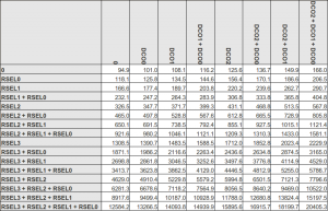
The following table shows the 128 discrete frequencies generated on a MSP430G2231 MCU (click to enlarge) by the different combinations of the DCO and RSEL bits.
The above table can also be downloaded here in Excel format: MSP430DCOFrequencies.xls
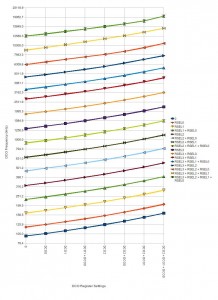
The chart below shows the 128 frequencies with different DCO and RSEL settings.
For instance, the following code would generate a DCO frequency of roughly 15.8 MHz:
|
1 |
|
Please keep in mind that the frequencies in the chart above are likely to vary somewhat among different chips as they are not calibrated. You should only use this chart to derive the approximate DCO frequency. On different chips, these frequencies can vary 5% to 10% with the same DCO and RSEL settings.


 提升卡
提升卡 变色卡
变色卡 千斤顶
千斤顶


 京公网安备 11010802033920号