【Follow me第二季第2期】Arduino UNO R4 WiFi跟我一起练
[复制链接]
本帖最后由 90houyidai 于 2024-11-1 23:16 编辑
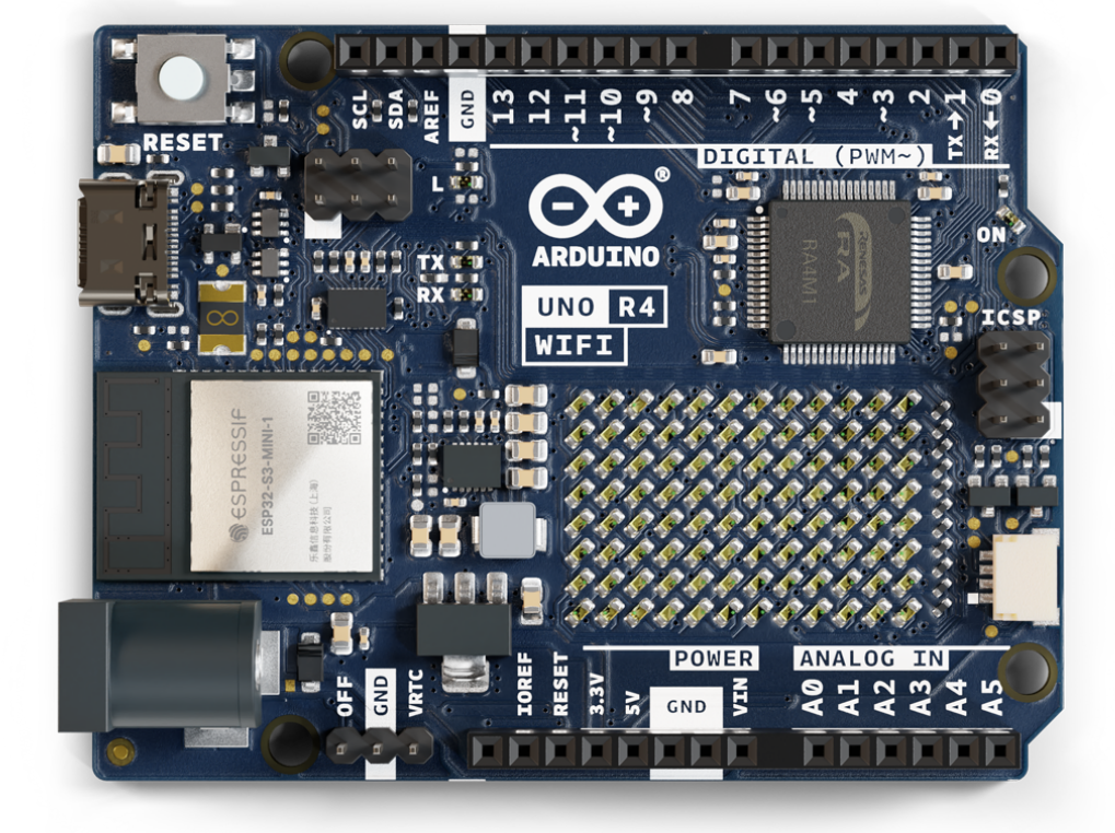
Arduino UNO R4 WiFi 是一款基于32位Arm® Cortex®-M4 Renesas RA4M1微控制器,具有用于 Wi-Fi® 和蓝牙连接的ESP32模块,具备强大的计算能力和多种连接功能。该板SRAM 32kB,闪存256kB,时钟频率为48MHz,USB端口升级为USB-C,并且最大电源供应电压增加到24V。该板提供了一个CAN总线,允许用户通过连接多个扩展板来最小化布线并执行不同的任务。板载的Qwiic 连接器可以方便地创建即插即用风格的项目。
使用到资料
• Arduino UNO R4 WiFi数据手册
• Arduino UNO R4 WiFi原理图
• Arduino UNO R4 WiFi引脚图
• RA4M1数据手册
• RA4M1硬件用户手册
• SHT40数据手册
Temp Graph with UNO R4 and SHT40 - Software Deep Dive - Hackster.io
Home Assistant获取DHT11温湿度-CSDN博客
开发环境:Arduino IDE Nightly Builds
使用到的库:
Adafruit_SHT4x、ArduinoMqttClient
使用到的硬件:
主板:Arduino UNO R4 WiFi(核心板)
扩展板:4885(SHT40温湿度传感器扩展板)
缆线:PRT-14426(Qwiic缆线-50mm)
简单开箱
入门任务(必做):搭建环境并开启第一步Blink / 串口打印Hello EEWorld!
#include "Arduino_LED_Matrix.h"

// the setup function runs once when you press reset or power the board
void setup() {
  // initialize digital pin LED_BUILTIN as an output.
  pinMode(LED_BUILTIN, OUTPUT);
  Serial.begin(115200);
}

// the loop function runs over and over again forever
void loop() {
  Serial.write("Hello ");
  digitalWrite(LED_BUILTIN, HIGH);  // turn the LED on (HIGH is the voltage level)
  delay(500);                      // wait for a second
  Serial.write("EEWorld\r\n");
  digitalWrite(LED_BUILTIN, LOW);   // turn the LED off by making the voltage LOW
  delay(500);                      // wait for a second
}
基础任务(必做):
一、驱动12x8点阵LED;
#include "Arduino_LED_Matrix.h"
#include <stdint.h>
#include "opamp.h"
ArduinoLEDMatrix matrix;

const uint32_t animation[][4] = {
	{
		0x2006,
		0x200200,
		0x20070000,
		1000
	},
	{
		0x6009,
		0x200400,
		0x800f0000,
		1000
	},
	{
		0xe001,
		0xe00100,
		0x100e0000,
		1000
	}
};
// the setup function runs once when you press reset or power the board
void setup() {
  // initialize digital pin LED_BUILTIN as an output.
  pinMode(LED_BUILTIN, OUTPUT);
  Serial.begin(115200);
  matrix.autoscroll(2000);
  matrix.loadSequence(animation);
  matrix.begin();
  // turn on autoscroll to avoid calling next() to show the next frame; the parameter is in milliseconds
  //matrix.autoscroll(2000);
  matrix.play(true);


  OPAMP.begin(OPAMP_SPEED_HIGHSPEED);

}

// the loop function runs over and over again forever
void loop() {
  Serial.write("Hello ");
  digitalWrite(LED_BUILTIN, HIGH);  // turn the LED on (HIGH is the voltage level)
  delay(1000);                      // wait for a second
  Serial.write("EEWorld\r\n");
  digitalWrite(LED_BUILTIN, LOW);   // turn the LED off by making the voltage LOW
  delay(1000);                      // wait for a second
}
可以使用https://ledmatrix-editor.arduino.cc/生成需要的显示图形和动画
二、用DAC生成正弦波;
#include "analogWave.h" // Include the library for analog waveform generation

analogWave wave(DAC);   // Create an instance of the analogWave class, using the DAC pin

int freq = 10;  // in hertz, change accordingly

void setup() {
  Serial.begin(115200);  // Initialize serial communication at a baud rate of 115200
  wave.sine(freq);       // Generate a sine wave with the initial frequency
}

void loop() {
  // Read an analog value from pin A5 and map it to a frequency range
  //freq = map(analogRead(A5), 0, 1024, 0, 10000);

  // Print the updated frequency to the serial monitor
  Serial.println("Frequency is now " + String(freq) + " hz");

  wave.freq(freq);  // Set the frequency of the waveform generator to the updated value
  delay(1000);      // Delay for one second before repeating
}
三、用OPAMP放大DAC信号;
#include "Arduino_LED_Matrix.h"
#include <stdint.h>
#include <OPAMP.h>
ArduinoLEDMatrix matrix;

const uint32_t animation[][4] = {
	{
		0x2006,
		0x200200,
		0x20070000,
		1000
	},
	{
		0x6009,
		0x200400,
		0x800f0000,
		1000
	},
	{
		0xe001,
		0xe00100,
		0x100e0000,
		1000
	}
};
uint16_t sin_index;
//正弦波单个周期的点数
#define POINT_NUM 32
/* 波形数据 -----------------------------------------------*/
const uint16_t Sine12bit[POINT_NUM] = {
    2048  , 2460  , 2856  , 3218  , 3532  , 3786  , 3969  , 4072  ,
    4093  , 4031  , 3887  , 3668  , 3382  , 3042  , 2661  , 2255  ,
    1841  , 1435  , 1054  , 714   , 428   , 209   , 65    , 3     ,
    24    , 127   , 310   , 564   , 878   , 1240  , 1636  , 2048
};
// the setup function runs once when you press reset or power the board
void setup() {
  // initialize digital pin LED_BUILTIN as an output.
  pinMode(LED_BUILTIN, OUTPUT);
  Serial.begin(115200);
  matrix.autoscroll(2000);
  matrix.loadSequence(animation);
  matrix.begin();
  // turn on autoscroll to avoid calling next() to show the next frame; the parameter is in milliseconds
  //matrix.autoscroll(2000);
  matrix.play(true);

  analogWriteResolution(12);//change this write resolution up to 12-bits
  OPAMP.begin(OPAMP_SPEED_HIGHSPEED);

}

// the loop function runs over and over again forever
void loop() {
  #if 0
  Serial.write("Hello ");
  digitalWrite(LED_BUILTIN, HIGH);  // turn the LED on (HIGH is the voltage level)
  analogWrite(A0, 123);
  delay(1000);                      // wait for a second
  Serial.write("EEWorld\r\n");
  digitalWrite(LED_BUILTIN, LOW);   // turn the LED off by making the voltage LOW
  analogWrite(A0, 0);
  Serial.write("A1_input:%d\r\n",analogRead(A1));
  delay(1000);                      // wait for a second
  #else
  analogWrite(A5, Sine12bit[sin_index++%POINT_NUM]>>2);//输出正弦波
  delay(1);
  #endif
}

四、用ADC采集并且打印数据到串口等其他接口可上传到上位机显示曲线
#include "analogWave.h"
analogWave wave(DAC);
int freq = 1000;
// These constants won't change. They're used to give names to the pins used:
const int analogInPin = A1;  // Analog input pin that the potentiometer is attached to
const int analogOutPin = 9;  // Analog output pin that the LED is attached to

int sensorValue = 0;  // value read from the pot
int outputValue = 0;  // value output to the PWM (analog out)

void setup() {
  // initialize serial communications at 9600 bps:
  Serial.begin(115200);
  wave.sine(freq);
}

void loop() {
  // read the analog in value:
  sensorValue = analogRead(analogInPin);
  // map it to the range of the analog out:
  outputValue = map(sensorValue, 0, 1023, 0, 255);
  // change the analog out value:
  analogWrite(analogOutPin, outputValue);

  // print the results to the Serial Monitor:
  //Serial.print("sensor = ");
  Serial.println(sensorValue);
  //Serial.print("\t output = ");
  //Serial.println(outputValue);

  // wait 2 milliseconds before the next loop for the analog-to-digital
  // converter to settle after the last reading:
  delay(2);
}
进阶任务(必做):通过Wi-Fi,利用MQTT协议接入到开源的智能家居平台HA(HomeAssistant)
#include <ArduinoMqttClient.h>
#if defined(ARDUINO_SAMD_MKRWIFI1010) || defined(ARDUINO_SAMD_NANO_33_IOT) || defined(ARDUINO_AVR_UNO_WIFI_REV2)
  #include <WiFiNINA.h>
#elif defined(ARDUINO_SAMD_MKR1000)
  #include <WiFi101.h>
#elif defined(ARDUINO_ARCH_ESP8266)
  #include <ESP8266WiFi.h>
#elif defined(ARDUINO_PORTENTA_H7_M7) || defined(ARDUINO_NICLA_VISION) || defined(ARDUINO_ARCH_ESP32) || defined(ARDUINO_GIGA) || defined(ARDUINO_OPTA)
  #include <WiFi.h>
#elif defined(ARDUINO_PORTENTA_C33)
  #include <WiFiC3.h>
#elif defined(ARDUINO_UNOR4_WIFI)
  #include <WiFiS3.h>
#endif

#include "arduino_secrets.h"
///////please enter your sensitive data in the Secret tab/arduino_secrets.h
char ssid[] = SECRET_SSID;    // your network SSID (name)
char pass[] = SECRET_PASS;    // your network password (use for WPA, or use as key for WEP)

// To connect with SSL/TLS:
// 1) Change WiFiClient to WiFiSSLClient.
// 2) Change port value from 1883 to 8883.
// 3) Change broker value to a server with a known SSL/TLS root certificate
//    flashed in the WiFi module.

WiFiClient wifiClient;
MqttClient mqttClient(wifiClient);

const char broker[] = "192.168.110.23";//"core-mosquitto";//"test.mosquitto.org";
int        port     = 1883;
const char topic[]  = "office/sensor_sht40";

const long interval = 1000;
unsigned long previousMillis = 0;

int count = 0;

void setup() {
  //Initialize serial and wait for port to open:
  Serial.begin(115200);
  while (!Serial) {
    ; // wait for serial port to connect. Needed for native USB port only
  }

  // attempt to connect to WiFi network:
  Serial.print("Attempting to connect to WPA SSID: ");
  Serial.println(ssid);
  while (WiFi.begin(ssid, pass) != WL_CONNECTED) {
    // failed, retry
    Serial.print(".");
    delay(5000);
  }

  Serial.println("You're connected to the network");
  Serial.println();
  Serial.println(WiFi.localIP());

  // You can provide a unique client ID, if not set the library uses Arduino-millis()
  // Each client must have a unique client ID
   mqttClient.setId("clientId");

  // You can provide a username and password for authentication
   mqttClient.setUsernamePassword("uno", "uno");

  Serial.print("Attempting to connect to the MQTT broker: ");
  Serial.println(broker);

  if (!mqttClient.connect(broker, port)) {
    Serial.print("MQTT connection failed! Error code = ");
    Serial.println(mqttClient.connectError());

    while (1);
  }

  Serial.println("You're connected to the MQTT broker!");
  Serial.println();
}

void loop() {
  // call poll() regularly to allow the library to send MQTT keep alives which
  // avoids being disconnected by the broker
  mqttClient.poll();

  // to avoid having delays in loop, we'll use the strategy from BlinkWithoutDelay
  // see: File -> Examples -> 02.Digital -> BlinkWithoutDelay for more info
  unsigned long currentMillis = millis();

  if (currentMillis - previousMillis >= interval) {
    // save the last time a message was sent
    previousMillis = currentMillis;

    Serial.print("Sending message to topic: ");
    Serial.println(topic);
    Serial.print("temperature: ");
    Serial.println(count);
    Serial.print("humidity: ");
    Serial.println(count);

    // send message, the Print interface can be used to set the message contents
    mqttClient.beginMessage(topic);
    mqttClient.print("temperature: ");
    mqttClient.print(count);
    mqttClient.print("humidity: ");
    mqttClient.print(count);
    mqttClient.endMessage();

    Serial.println();

    count++;
  }
}
扩展任务:通过外部SHT40温湿度传感器,上传温湿度到HA,通过HA面板显示数据
#include <ArduinoMqttClient.h>
#if defined(ARDUINO_SAMD_MKRWIFI1010) || defined(ARDUINO_SAMD_NANO_33_IOT) || defined(ARDUINO_AVR_UNO_WIFI_REV2)
  #include <WiFiNINA.h>
#elif defined(ARDUINO_SAMD_MKR1000)
  #include <WiFi101.h>
#elif defined(ARDUINO_ARCH_ESP8266)
  #include <ESP8266WiFi.h>
#elif defined(ARDUINO_PORTENTA_H7_M7) || defined(ARDUINO_NICLA_VISION) || defined(ARDUINO_ARCH_ESP32) || defined(ARDUINO_GIGA) || defined(ARDUINO_OPTA)
  #include <WiFi.h>
#elif defined(ARDUINO_PORTENTA_C33)
  #include <WiFiC3.h>
#elif defined(ARDUINO_UNOR4_WIFI)
  #include <WiFiS3.h>
#endif

#include "Adafruit_SHT4x.h"
#include "arduino_secrets.h"

///////please enter your sensitive data in the Secret tab/arduino_secrets.h
char ssid[] = SECRET_SSID;    // your network SSID (name)
char pass[] = SECRET_PASS;    // your network password (use for WPA, or use as key for WEP)

// To connect with SSL/TLS:
// 1) Change WiFiClient to WiFiSSLClient.
// 2) Change port value from 1883 to 8883.
// 3) Change broker value to a server with a known SSL/TLS root certificate
//    flashed in the WiFi module.

WiFiClient wifiClient;
MqttClient mqttClient(wifiClient);

const char broker[] = "homeassistant.local";//"core-mosquitto";//"test.mosquitto.org";
int        port     = 1883;
const char topic[]  = "office/sensor_sht40";

const long interval = 1000;
unsigned long previousMillis = 0;

int count = 0;
Adafruit_SHT4x sht4 = Adafruit_SHT4x();
float temperature_date,humidity_date;
sensors_event_t humidity, temp;
static TwoWire& SHT_I2C_INTERFACE = Wire1; // Wire1 = Uno R4 QWIIC port

void setup() {
  //Initialize serial and wait for port to open:
  Serial.begin(115200);
  while (!Serial) {
    ; // wait for serial port to connect. Needed for native USB port only
  }

  Serial.println("SHT40 test");
  if (! sht4.begin(&SHT_I2C_INTERFACE)) {
    Serial.println("Couldn't find SHT40");
    while (1) delay(1);
  }

  Serial.println("Found SHT40 sensor");
  Serial.print("Serial number 0x");
  Serial.println(sht4.readSerial(), HEX);

  // You can have 3 different precisions, higher precision takes longer
  sht4.setPrecision(SHT4X_HIGH_PRECISION);
  switch (sht4.getPrecision()) {
     case SHT4X_HIGH_PRECISION:
       Serial.println("High precision");
       break;
     case SHT4X_MED_PRECISION:
       Serial.println("Med precision");
       break;
     case SHT4X_LOW_PRECISION:
       Serial.println("Low precision");
       break;
  }

  // You can have 6 different heater settings
  // higher heat and longer times uses more power
  // and reads will take longer too!
  sht4.setHeater(SHT4X_NO_HEATER);
  switch (sht4.getHeater()) {
     case SHT4X_NO_HEATER:
       Serial.println("No heater");
       break;
     case SHT4X_HIGH_HEATER_1S:
       Serial.println("High heat for 1 second");
       break;
     case SHT4X_HIGH_HEATER_100MS:
       Serial.println("High heat for 0.1 second");
       break;
     case SHT4X_MED_HEATER_1S:
       Serial.println("Medium heat for 1 second");
       break;
     case SHT4X_MED_HEATER_100MS:
       Serial.println("Medium heat for 0.1 second");
       break;
     case SHT4X_LOW_HEATER_1S:
       Serial.println("Low heat for 1 second");
       break;
     case SHT4X_LOW_HEATER_100MS:
       Serial.println("Low heat for 0.1 second");
       break;
  }


  // attempt to connect to WiFi network:
  Serial.print("Attempting to connect to WPA SSID: ");
  Serial.println(ssid);
  while (WiFi.begin(ssid, pass) != WL_CONNECTED) {
    // failed, retry
    Serial.print(".");
    delay(5000);
  }

  Serial.println("You're connected to the network");
  Serial.println();
  Serial.println(WiFi.localIP());

  // You can provide a unique client ID, if not set the library uses Arduino-millis()
  // Each client must have a unique client ID
   mqttClient.setId("clientId");

  // You can provide a username and password for authentication
   mqttClient.setUsernamePassword("uno", "uno");

  Serial.print("Attempting to connect to the MQTT broker: ");
  Serial.println(broker);

  if (!mqttClient.connect(broker, port)) {
    Serial.print("MQTT connection failed! Error code = ");
    Serial.println(mqttClient.connectError());

    while (1);
  }

  Serial.println("You're connected to the MQTT broker!");
  Serial.println();
}

void loop() {
  // call poll() regularly to allow the library to send MQTT keep alives which
  // avoids being disconnected by the broker
  mqttClient.poll();

  // to avoid having delays in loop, we'll use the strategy from BlinkWithoutDelay
  // see: File -> Examples -> 02.Digital -> BlinkWithoutDelay for more info
  unsigned long currentMillis = millis();

  if (currentMillis - previousMillis >= interval) {
    // save the last time a message was sent
    previousMillis = currentMillis;

    Serial.print("Sending message to topic: ");
    Serial.println(topic);
    // Serial.print("temperature:");
    // Serial.println(temperature_date);
    // Serial.print("humidity: ");
    // Serial.println(humidity_date);
    uint32_t timestamp = millis();
    sht4.getEvent(&humidity, &temp);// populate temp and humidity objects with fresh data
    timestamp = millis() - timestamp;

    Serial.print("Temperature: "); Serial.print(temp.temperature); Serial.println(" degrees C");
    Serial.print("Humidity: "); Serial.print(humidity.relative_humidity); Serial.println("% rH");

    Serial.print("Read duration (ms): ");
    Serial.println(timestamp);
    temperature_date=temp.temperature;
    humidity_date=humidity.relative_humidity;

    // send message, the Print interface can be used to set the message contents
    mqttClient.beginMessage(topic);
    mqttClient.println("{");
    mqttClient.print("   \"temperature\":");
    mqttClient.print(temperature_date);
    mqttClient.println(",");
    mqttClient.print("   \"humidity\":");
    mqttClient.println(humidity_date);
    mqttClient.print("}");
    mqttClient.endMessage();

    Serial.println();


    count+=0.01;
  }
}
软件流程图
代码包
(4)对本活动的心得体会(包括意见或建议)
本次活动让我接触到了Home Assistant 智能家居系统,这个系统感觉功能很强大,有很多好玩的插件,值得好好探索;
Arduino UNO R4 WiFi借助ESP32完成wifi操作,可玩性大大提高,MCU可以做自己的任务。
另外提个小意见,展示视频自我介绍好社恐
| 
 提升卡
提升卡 变色卡
变色卡 千斤顶
千斤顶
 1/6
1/6 


 京公网安备 11010802033920号
Copyright © 2005-2025 EEWORLD.com.cn, Inc. All rights reserved
京公网安备 11010802033920号
Copyright © 2005-2025 EEWORLD.com.cn, Inc. All rights reserved

