|
§ 6月2日更新NO.8
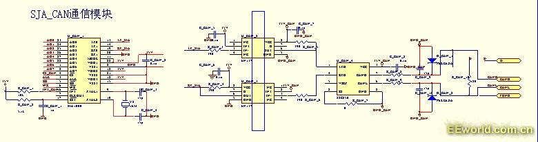
做这个CAN总线的扩展,采用模拟总线的方式,我们主要应用到IO口的两种功能,那就是常规的输入输出与IO口管脚中断功能。
下面对这两种功能运用到的寄存器与函数库中的内容作些许说明:
IO口的常规输入输出应用:
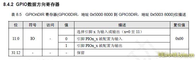
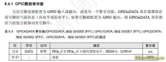
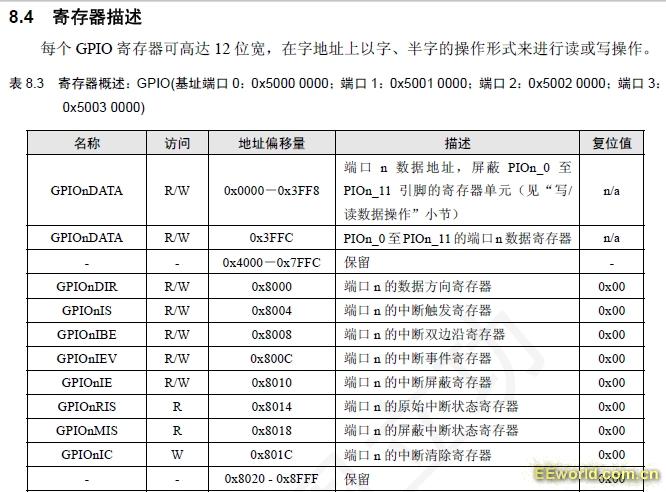
与这个功能相关的寄存器主要是GPIOnDATA、GPIOnDIR应用非常简单直接做样就可以
LPC_GPIO2->DIR = 0xFF;//为1的位则设置相应管教为输出模式
LPC_GPIO2->DATA |= 0xFF; //为1的位则设置相应管教输出1
库函数的相关封装的函数如下可以结合的理解下这两个寄存器的功能。
/*****************************************************************************
** Function name: GPIOSetDir
**
** Descriptions: Set the direction in GPIO port
**
** parameters: port num, bit position, direction (1 out, 0 input)
** Returned value: None
**
*****************************************************************************/
void GPIOSetDir( uint32_t portNum, uint32_t bitPosi, uint32_t dir )
{
/* if DIR is OUT(1), but GPIOx_DIR is not set, set DIR
to OUT(1); if DIR is IN(0), but GPIOx_DIR is set, clr
DIR to IN(0). All the other cases are ignored.
On port3(bit 0 through 3 only), no error protection if
bit value is out of range. */
switch ( portNum )
{
case PORT0:
if ( !(LPC_GPIO0->DIR & (0x1<<bitPosi)) && (dir == 1) )
LPC_GPIO0->DIR |= (0x1<<bitPosi);
else if ( (LPC_GPIO0->DIR & (0x1<<bitPosi)) && (dir == 0) )
LPC_GPIO0->DIR &= ~(0x1<<bitPosi);
break;
case PORT1:
if ( !(LPC_GPIO1->DIR & (0x1<<bitPosi)) && (dir == 1) )
LPC_GPIO1->DIR |= (0x1<<bitPosi);
else if ( (LPC_GPIO1->DIR & (0x1<<bitPosi)) && (dir == 0) )
LPC_GPIO1->DIR &= ~(0x1<<bitPosi);
break;
case PORT2:
if ( !(LPC_GPIO2->DIR & (0x1<<bitPosi)) && (dir == 1) )
LPC_GPIO2->DIR |= (0x1<<bitPosi);
else if ( (LPC_GPIO2->DIR & (0x1<<bitPosi)) && (dir == 0) )
LPC_GPIO2->DIR &= ~(0x1<<bitPosi);
break;
case PORT3:
if ( !(LPC_GPIO3->DIR & (0x1<<bitPosi)) && (dir == 1) )
LPC_GPIO3->DIR |= (0x1<<bitPosi);
else if ( (LPC_GPIO3->DIR & (0x1<<bitPosi)) && (dir == 0) )
LPC_GPIO3->DIR &= ~(0x1<<bitPosi);
break;
default:
break;
}
return;
}
可以发现基本上LPC_GPIOn->DIR是对这个的操作,也即是对GPIOnDIR的位设置,就实现哪个portNum的哪个bitPosi位的dir方向。较易理解。
/*****************************************************************************
** Function name: GPIOSetValue
**
** Descriptions: Set/clear a bitvalue in a specific bit position
** in GPIO portX(X is the port number.)
**
** parameters: port num, bit position, bit value
** Returned value: None
**
*****************************************************************************/
void GPIOSetValue( uint32_t portNum, uint32_t bitPosi, uint32_t bitVal )
{
/* if bitVal is 1, the bitPosi bit is set in the GPIOShadowPortx. Then
* GPIOShadowPortx is written to the I/O port register. */
switch ( portNum )
{
case PORT0:
if(bitVal)
GPIOShadowPort0 |= (1<<bitPosi);
else
GPIOShadowPort0 &= ~(1<<bitPosi);
/* Use of shadow prevents bit operation error if the read value
* (external hardware state) of a pin differs from the I/O latch
* value. A potential side effect is that other GPIO code in this
* project that is not aware of the shadow will have its GPIO
* state overwritten.
*/
LPC_GPIO0->DATA = GPIOShadowPort0;
break;
case PORT1:
if(bitVal)
GPIOShadowPort1 |= (1<<bitPosi);
else
GPIOShadowPort1 &= ~(1<<bitPosi);
LPC_GPIO1->DATA = GPIOShadowPort1;
break;
case PORT2:
if(bitVal)
GPIOShadowPort2 |= (1<<bitPosi);
else
GPIOShadowPort2 &= ~(1<<bitPosi);
LPC_GPIO2->DATA = GPIOShadowPort2;
break;
case PORT3:
if(bitVal)
GPIOShadowPort3 |= (1<<bitPosi);
else
GPIOShadowPort3 &= ~(1<<bitPosi);
LPC_GPIO3->DATA = GPIOShadowPort3;
break;
default:
break;
}
return;
}
可以发现基本上是对LPC_GPIOn->DATA寄存器的操作,以完成数据的输出。也不难理解,也就是GPIOnDATA、GPIOnDIR两个寄存器可以实现
IO口的管脚中断应用:
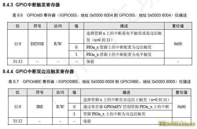
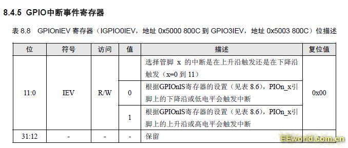
设置IO口的管脚中断其实主要相关的寄存器是GPIOnIS、GPIOnIBE、GPIOnIEV。
/*****************************************************************************
** Function name: GPIOSetInterrupt
**
** Descriptions: Set interrupt sense, event, etc.
** edge or level, 0 is edge, 1 is level
** single or double edge, 0 is single, 1 is double
** active high or low, etc.
**
** parameters: port num, bit position, sense, single/doube, polarity
** Returned value: None
**
*****************************************************************************/
void GPIOSetInterrupt( uint32_t portNum, uint32_t bitPosi, uint32_t sense,
uint32_t single, uint32_t event )
{
switch ( portNum )
{
case PORT0:
if ( sense == 0 )
{
LPC_GPIO0->IS &= ~(0x1<<bitPosi);
/* single or double only applies when sense is 0(edge trigger). */
if ( single == 0 )
LPC_GPIO0->IBE &= ~(0x1<<bitPosi);
else
LPC_GPIO0->IBE |= (0x1<<bitPosi);
}
else
LPC_GPIO0->IS |= (0x1<<bitPosi);
if ( event == 0 )
LPC_GPIO0->IEV &= ~(0x1<<bitPosi);
else
LPC_GPIO0->IEV |= (0x1<<bitPosi);
break;
。。。。。。。。。。。。。。。。。。
case PORT1://同上
。。。。。。。。。。。。。。。。。。
case PORT2: //同上
。。。。。。。。。。。。。。。。。。
case PORT3: //同上
。。。。。。。。。。。。。。。。。。
}
return;
}
这个函数就是依据如下:
GPIOnIS—位为0设置为边沿触发,位为1设置为电平触发。
GPIOnIBE--位为0设置为单状态触发(一种边沿状态或电平状态)由IEV决定,位为1设置为双边沿触发。
GPIOnIEV--位为0设置为下降沿或低电平触发,位为1设置为上升沿或高电平触发。
/*****************************************************************************
** Function name: GPIOIntEnable
**
** Descriptions: Enable Interrupt Mask for a port pin.
**
** parameters: port num, bit position
** Returned value: None
**
*****************************************************************************/
void GPIOIntEnable( uint32_t portNum, uint32_t bitPosi )
{
switch ( portNum )
{
case PORT0:
LPC_GPIO0->IE |= (0x1<<bitPosi);
break;
case PORT1:
LPC_GPIO1->IE |= (0x1<<bitPosi);
break;
case PORT2:
LPC_GPIO2->IE |= (0x1<<bitPosi);
break;
case PORT3:
LPC_GPIO3->IE |= (0x1<<bitPosi);
break;
default:
break;
}
return;
}
可以发现基本上是对GPIOnIE寄存器的设置:
GPIOnIE—位为0设置为中断被屏蔽,位为1设置为中断开启。
[[i] 本帖最后由 pepsi360 于 2010-6-2 11:41 编辑 [/i]] | 


 1/10
1/10 


 京公网安备 11010802033920号
Copyright © 2005-2025 EEWORLD.com.cn, Inc. All rights reserved
京公网安备 11010802033920号
Copyright © 2005-2025 EEWORLD.com.cn, Inc. All rights reserved
